Grove

09.14 – 12.14

 
Objectives
 

“Nest Studio: Grove” was a project that questioned the conventional architectural envelope and explored the possibility of a diffusive architecture. The studio was the cumulative effort of a dedicated group of students over the course of a 4-month term. During the first 3-months, individual studies were made into emerging technologies, materials, and systems. After these independent studies, students collaborated on a cohesive design that incorporated these systems. The studio was lead by Philip Beasley and was ultimately an exploration in fabrication and system design.

The result was a built section of a dining pavilion composed of plywood, BoPET, steel, glass, silicone, and acrylic glass. With the help of 2 Arduinos (one controlling an air-muscle system and the other controlling a sequence of LEDS responding to a motion sensor) the installation began to come to life through its organic gestures; creating a sense of interplay between itself and the subject.

in collaboration with Hasan Al Salman, Patrick Cheung, Christopher Glebe, Connie Lei, Georgiana Nicoara, Jake Read, Sara Torki, Cecylia Yan and Mengdie Zhang.

Axonometric view depicting repeatible module

Design Process

Diffusive Architecture

The built portion of this project was used as a means to explore larger ideas surrounding the capabilities of diffusive architecture. In the context of this studio, we began by re-imagining the accepted architectural envelope; one that is dictated by structure, climate, and ‘finish’. Instead, the envelope was thought of more abstractly:

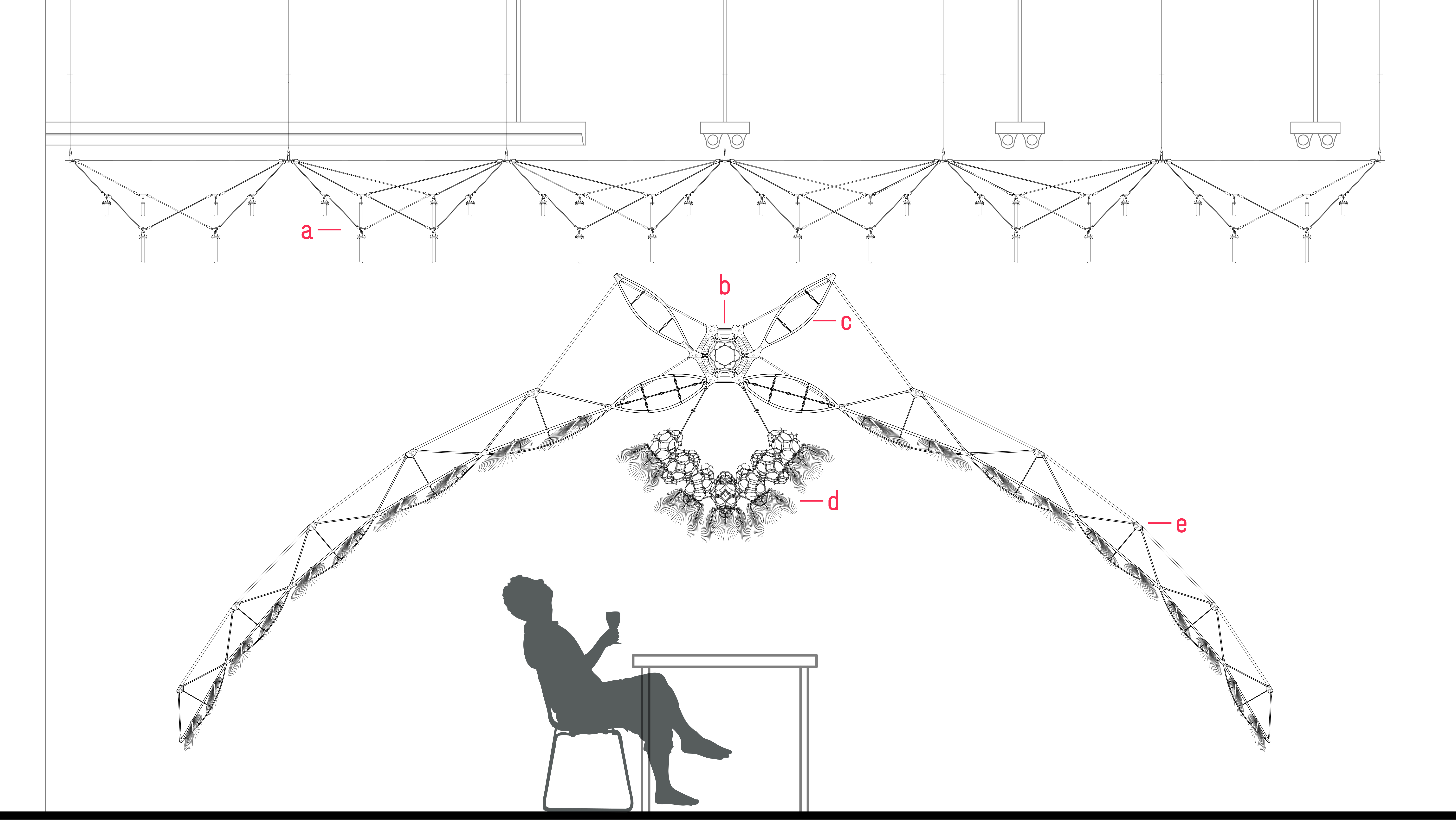
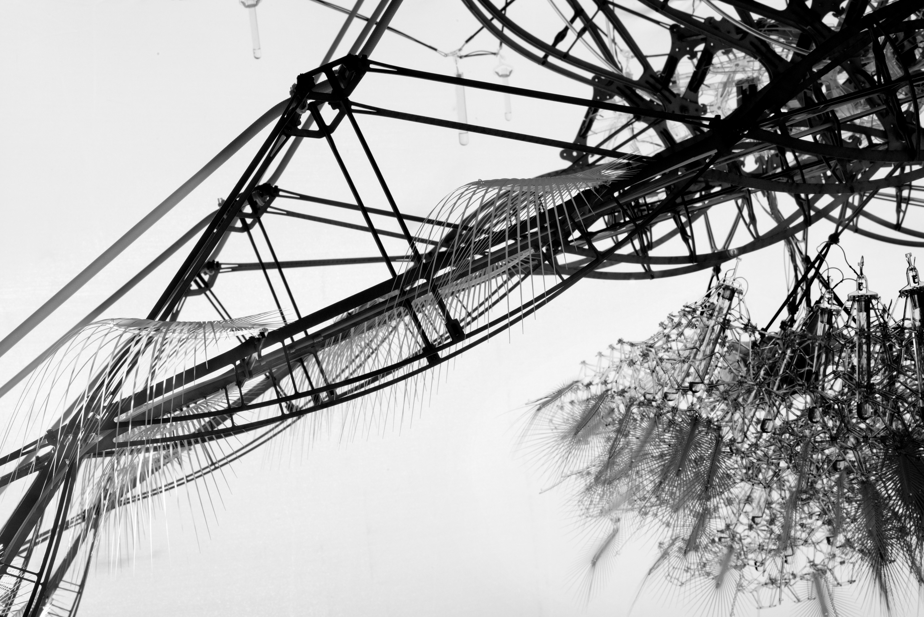
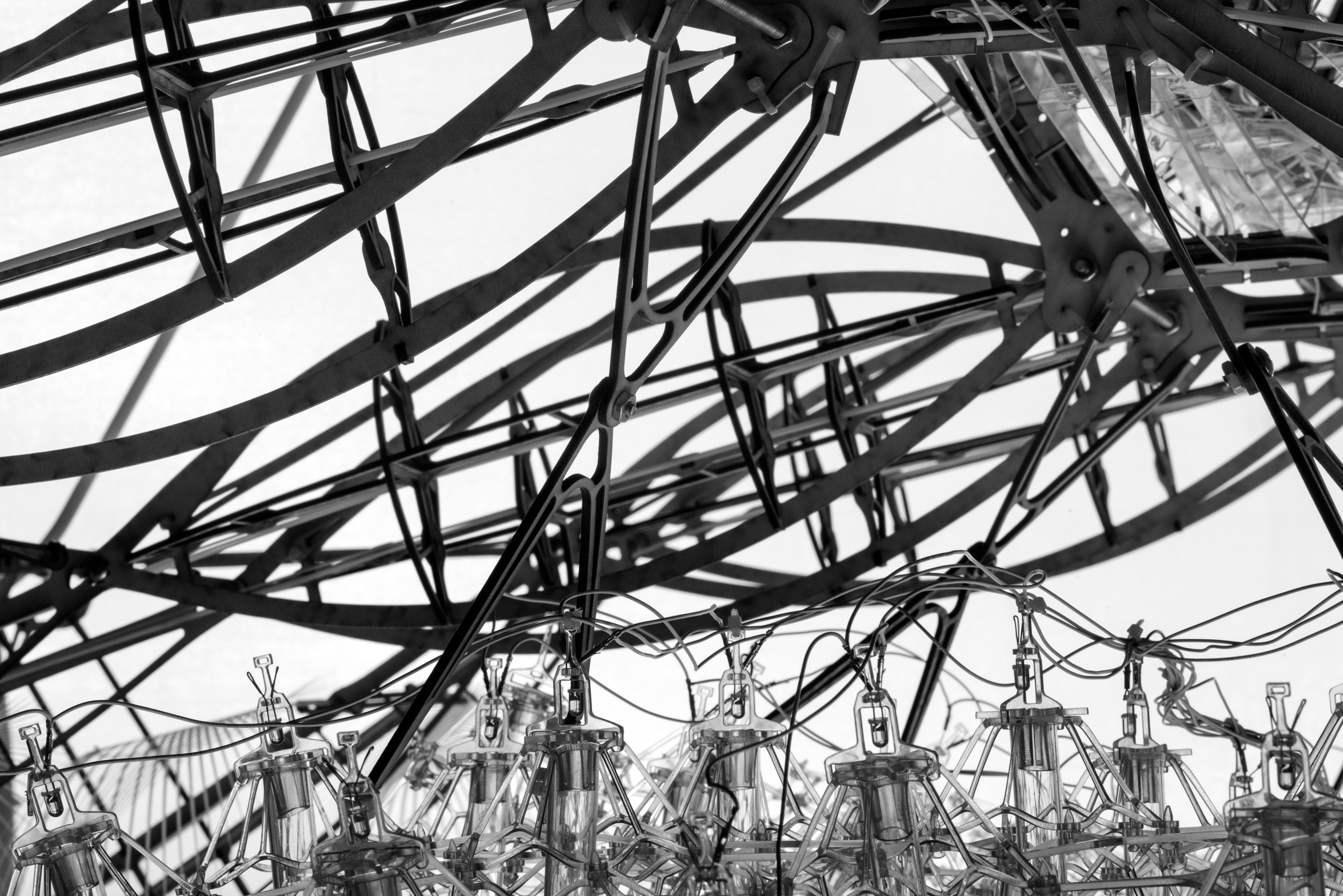
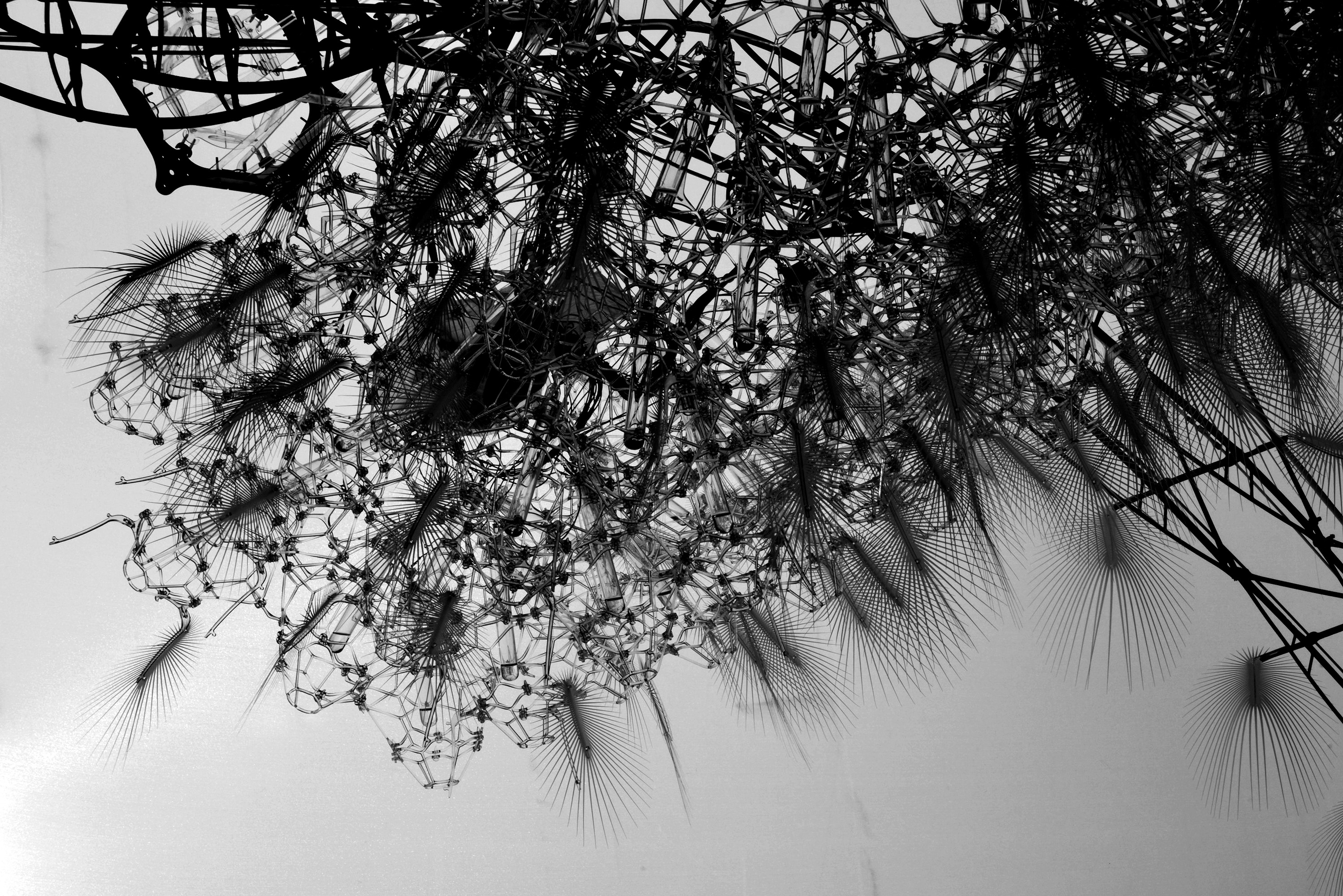
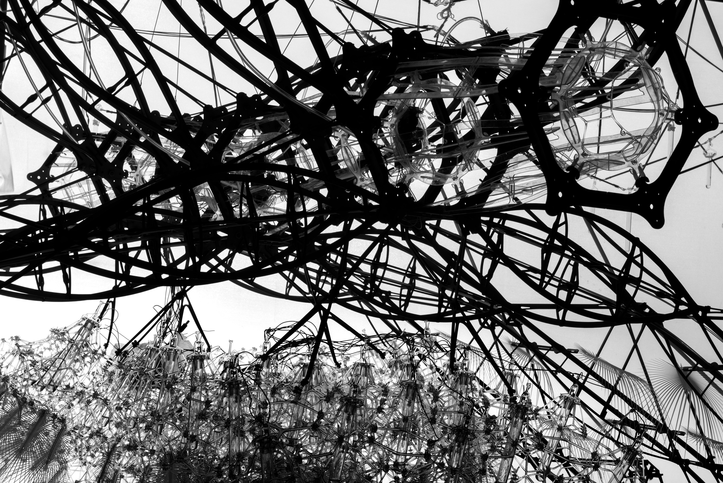
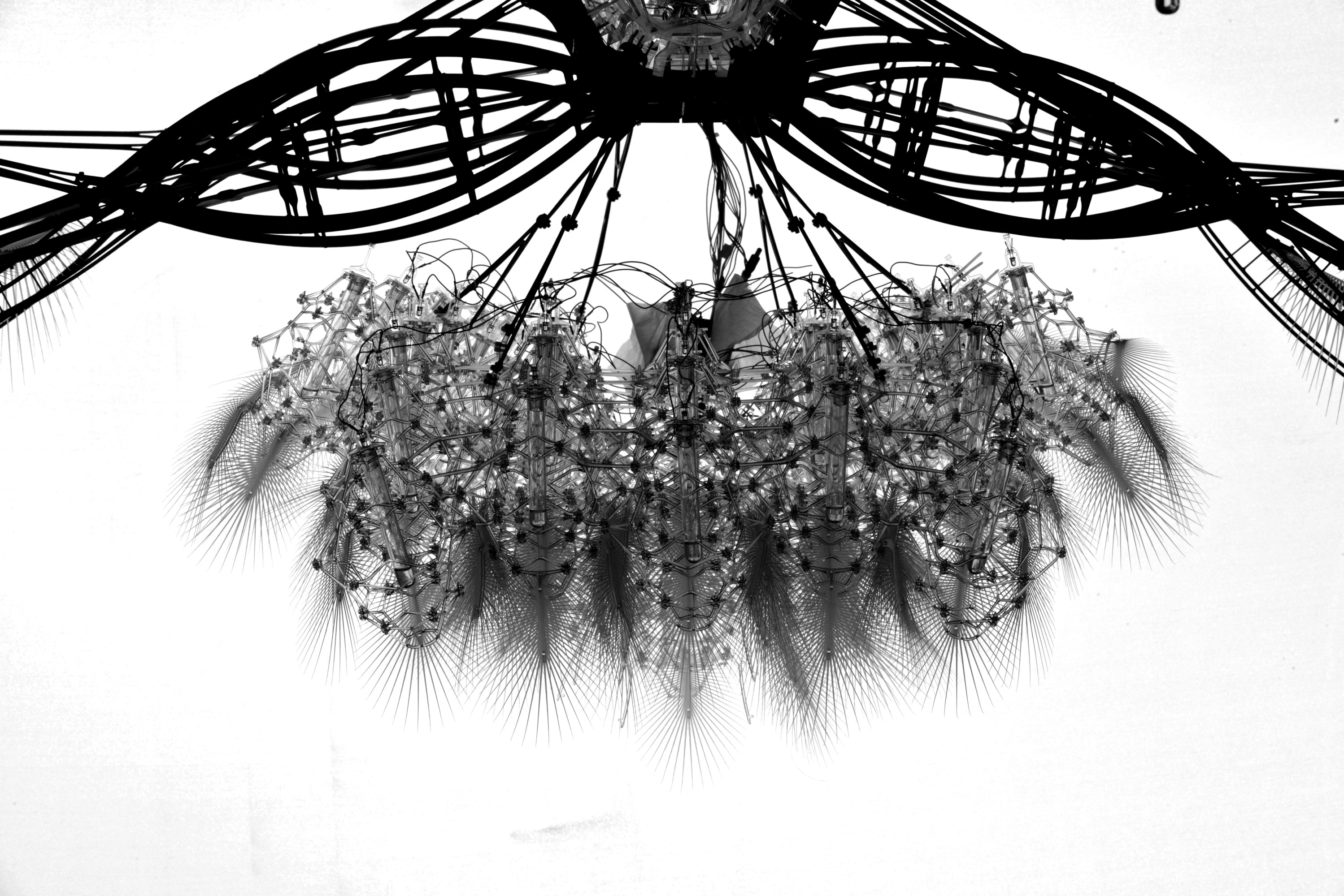
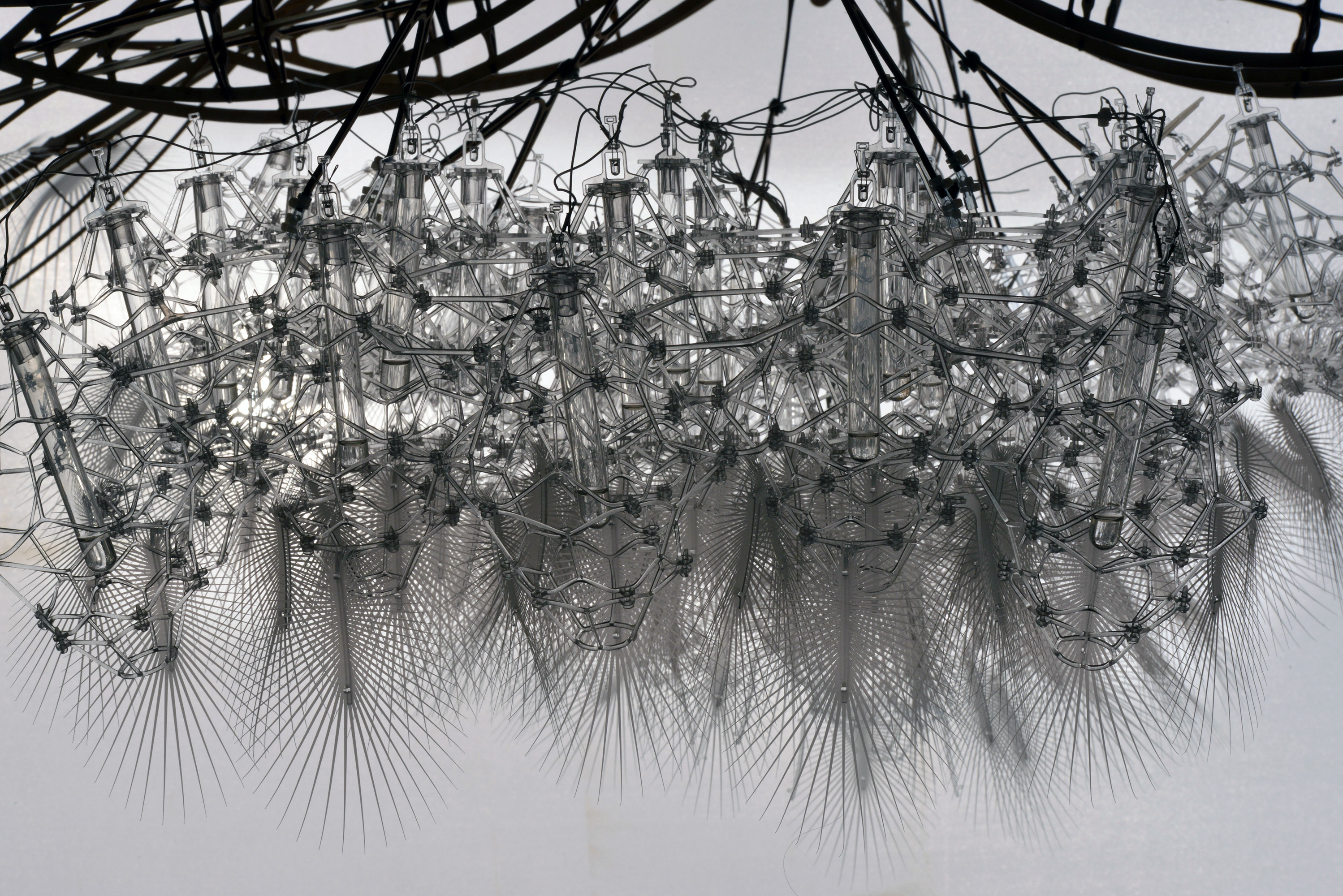
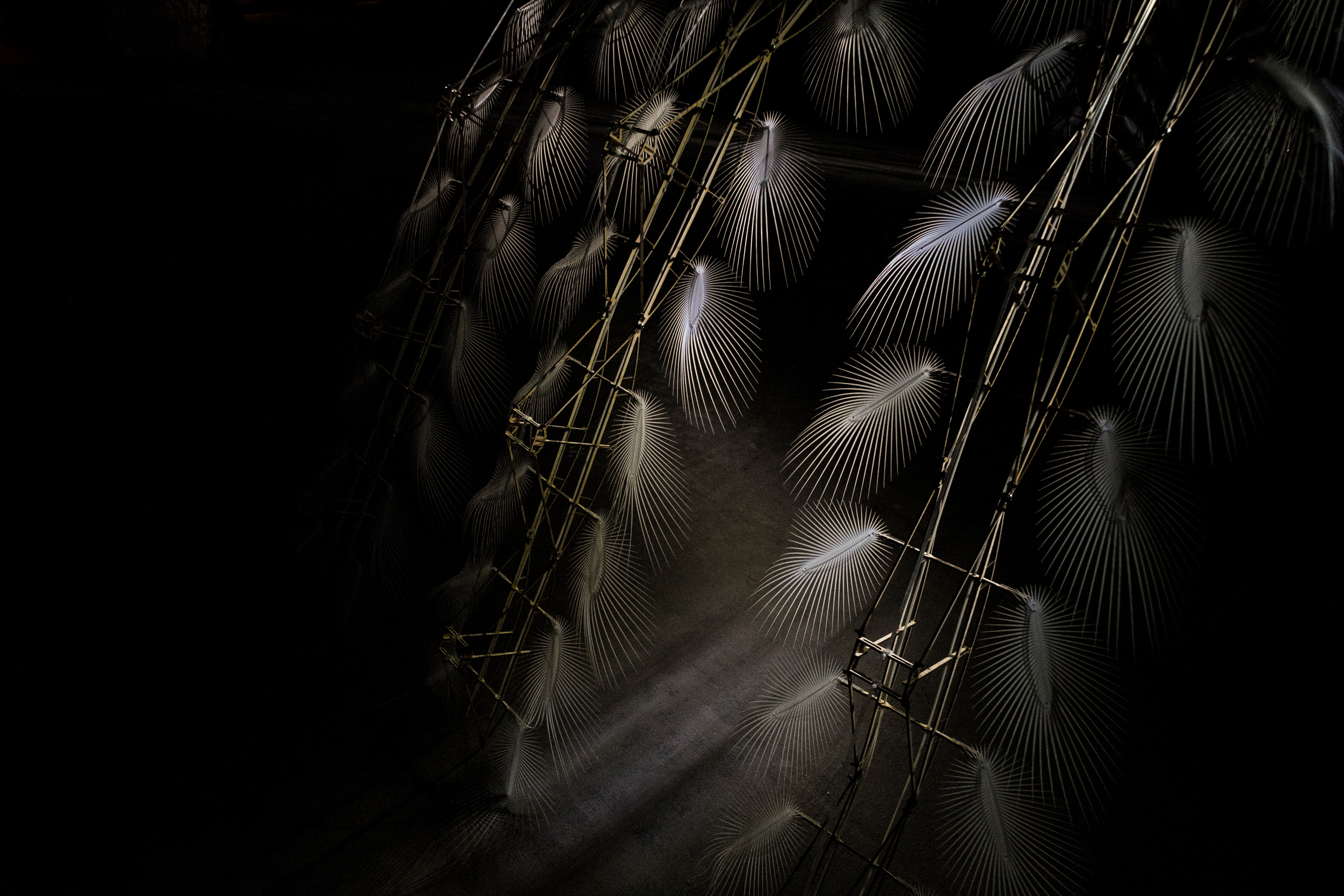
(a) The Veil: A wire diagrid suspended in space, reaching out to the furthest corners of the space it inhabits. At its central nodes, test tubes filled with various degrees of water are attached. The amount of water in the tube affects its weight, and the weight affects the amount of pressure put on the diagrid, ultimately shaping it.

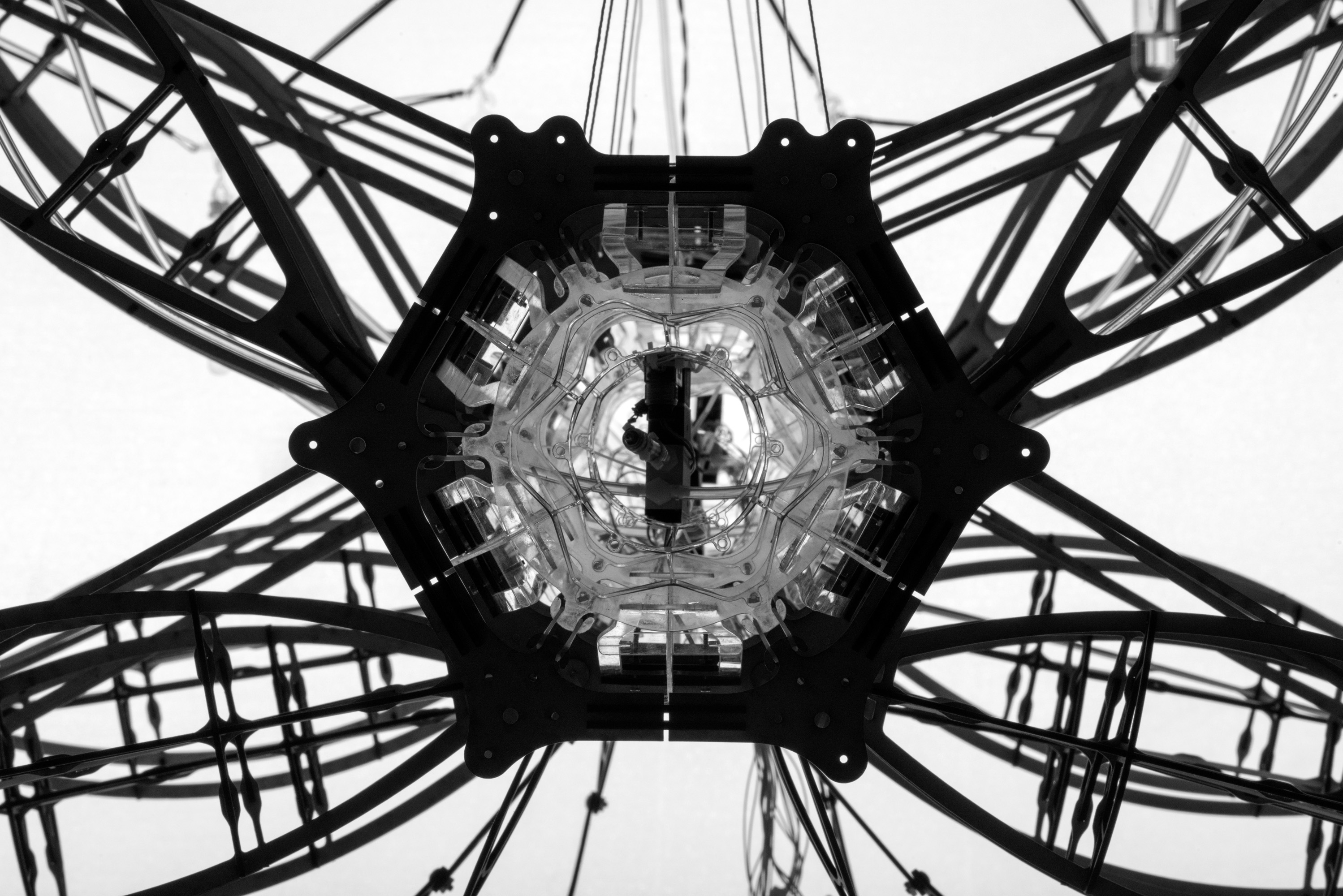
(b) The Spine: The strongest portion of the envelope is constructed fromt thick plywood, reinforced by steel rods. Each modular section attaches to its adjacent section through an elastic connection. This component remains largely static, but its elastic connection allows for a small degree of movement. This component is tethered to the ceiling and supports the structure beneath.

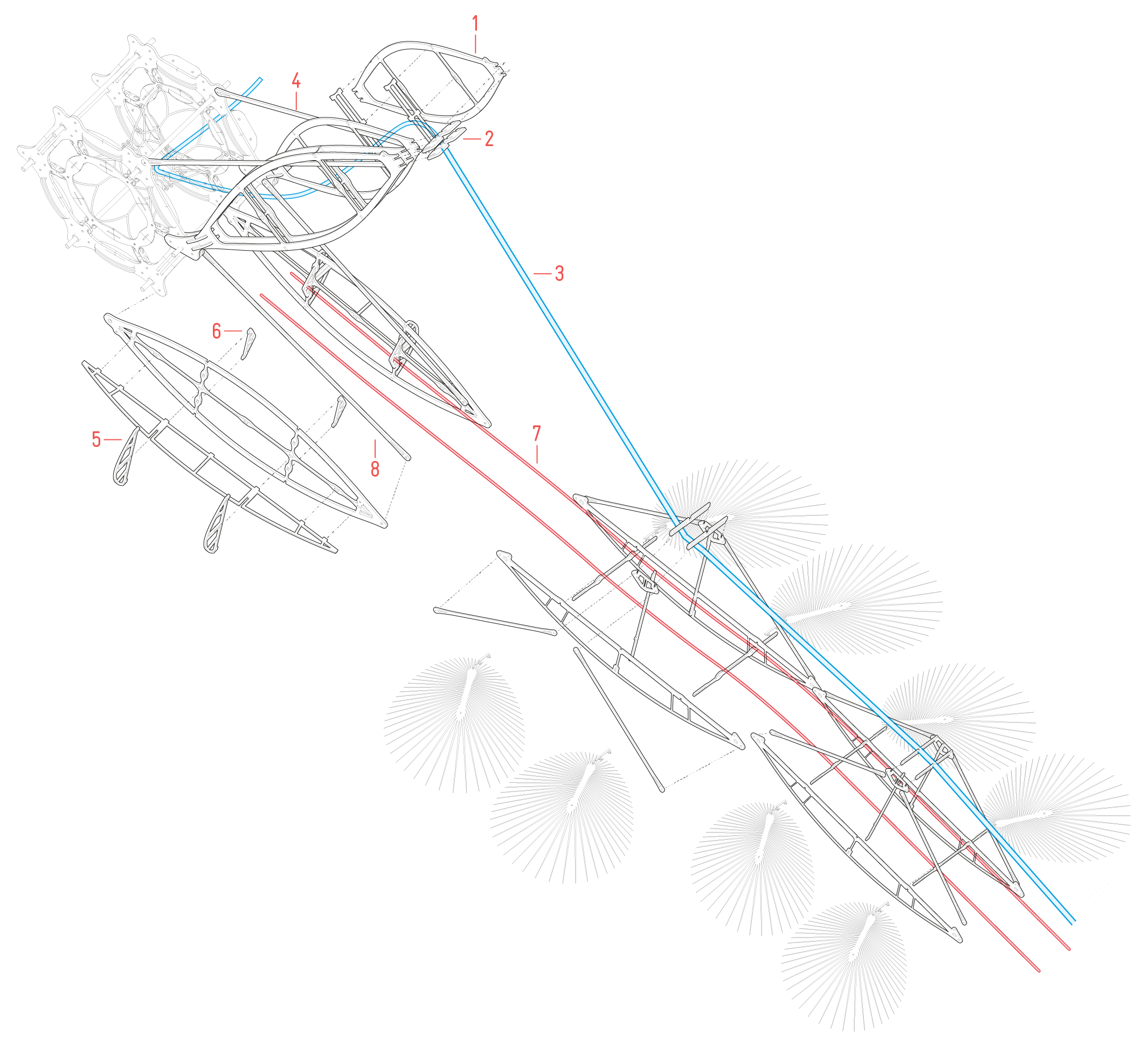
(c) The Shoulder: Composed of two critical elements, this portion of the structure acts to control the distribution of forces from an element in motion (the wing) to a static element (the spine).

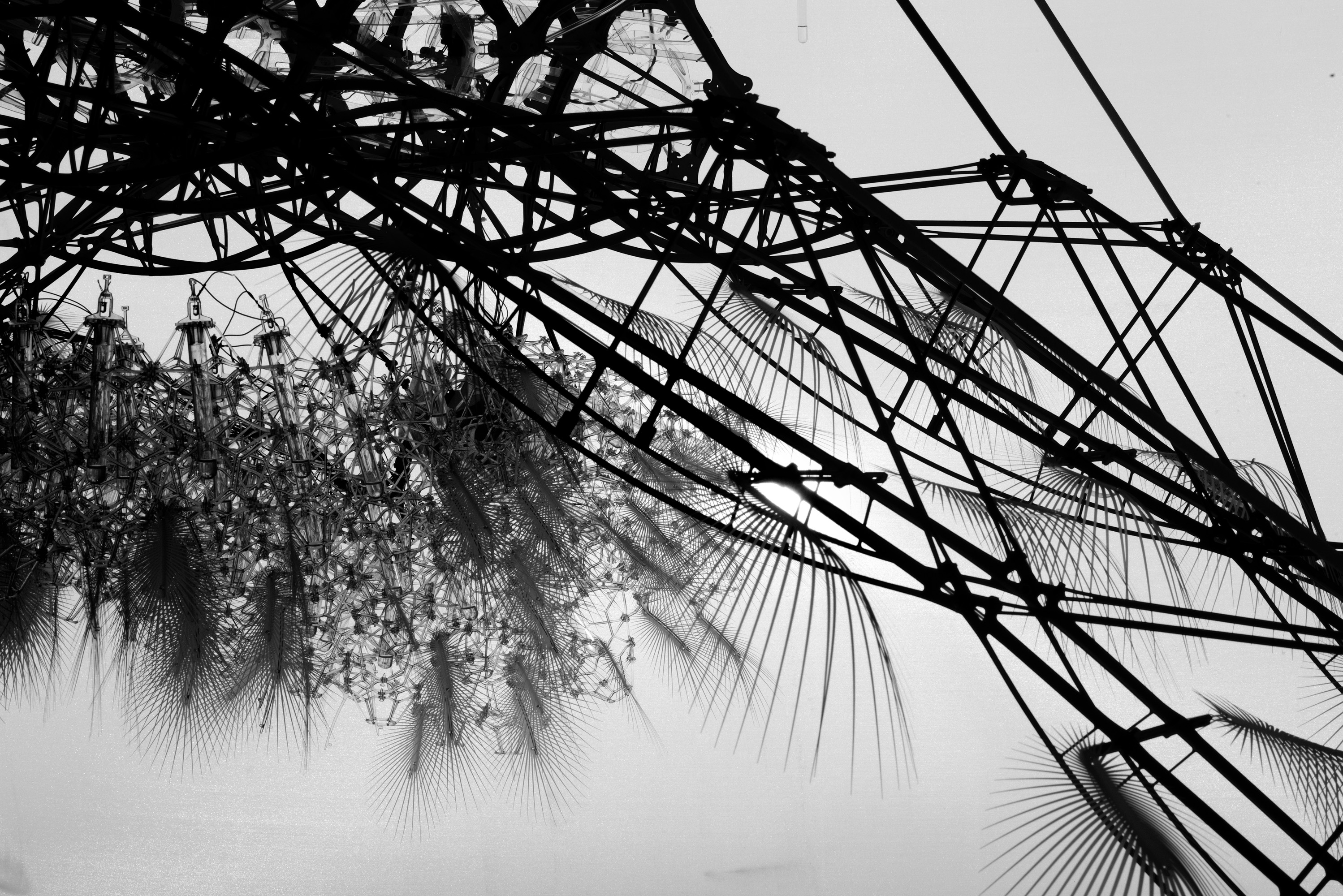
(c) The Filter: Sitting just above eye-level, the cloud is the most intricate portion of the installation. It is meant to be observed, touched and interacted with. Outfitted with motion-sensors, an Arduino script translates the movement of its occupants into flashes of light which closely resemble that of a storm cloud.

(d) The Wing: Composed of 5 similar components that decrease in size as they move from the shoulder towards the ground. The wing is light enough to move freely, but strong enough to withstand the force of the air-muscle system

Section / Typical

Plan / Aerial View

Independent Research
 

During the course of the studio, students were responsible for the independent research, development, and fabrication of their respective components, before they were consolidated. My independent research centered around ‘the shoulder’, a critical component which acted as a point of mediation between the kinetic energy experienced by the wing, and the stationary position of the spine. By successfully transferring the forces required to raise the wing in a purposeful manner towards the spine, we were able to limit any serious movement or swaying in the overall structure.

Upper Shoulder : Its function is to control the incredible force exerted by the air-muscle system on the spine. 2 sets of compression members (1) brace the spine and meet at central point (2) where the air-muscle (3) is securely fastened. These compressive members handle the force while the air-muscles are engaged. At rest, thin tensile members (4) hold the weight of the upper shoulder and some of the distributed weight of the wing.

Lower Shoulder : Its function is to resist movement in all directions. Bracing (5) in the X, Y, and Z direction ensures that the the piece will not rotate in any direction while the wing is in motion. This is crucial as it keeps the wing centred, and respectively allows the air-muscle to pull the wing upward in a clean, directional movement. Additional bracing (6) is used to secure the fibreglass-rods (7) in place. Similar to the upper shoulder, when the component is at rest it is supported by a thin tensile-member. (8)